Engineering · Jun 2025 – Present
Travel Remote Observatory
A portable, battery-powered 6″ Ritchey–Chrétien observatory that I can run on-site from its own Wi-Fi hotspot or from anywhere over a VPN, with custom power distribution and dew control.
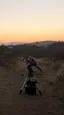
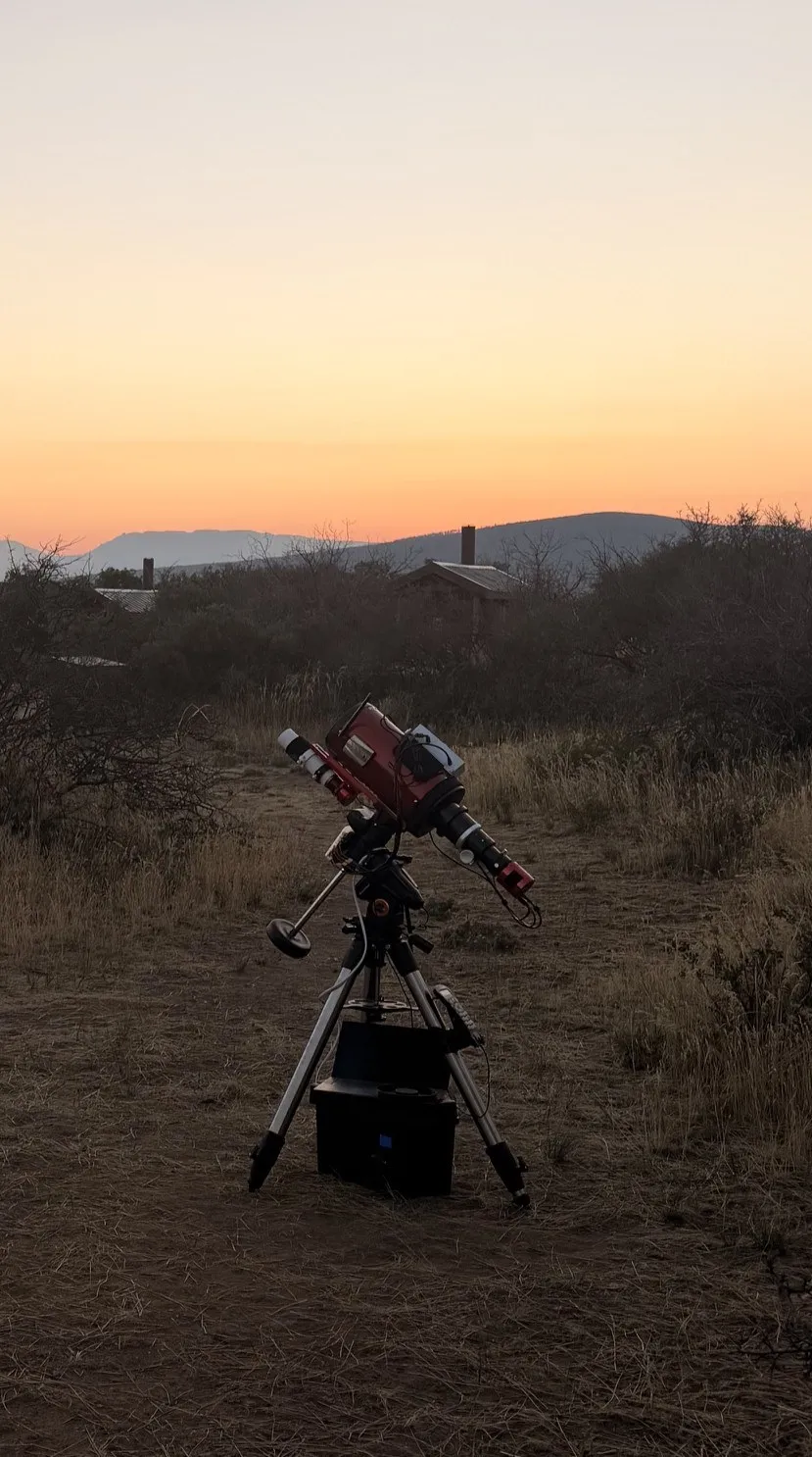
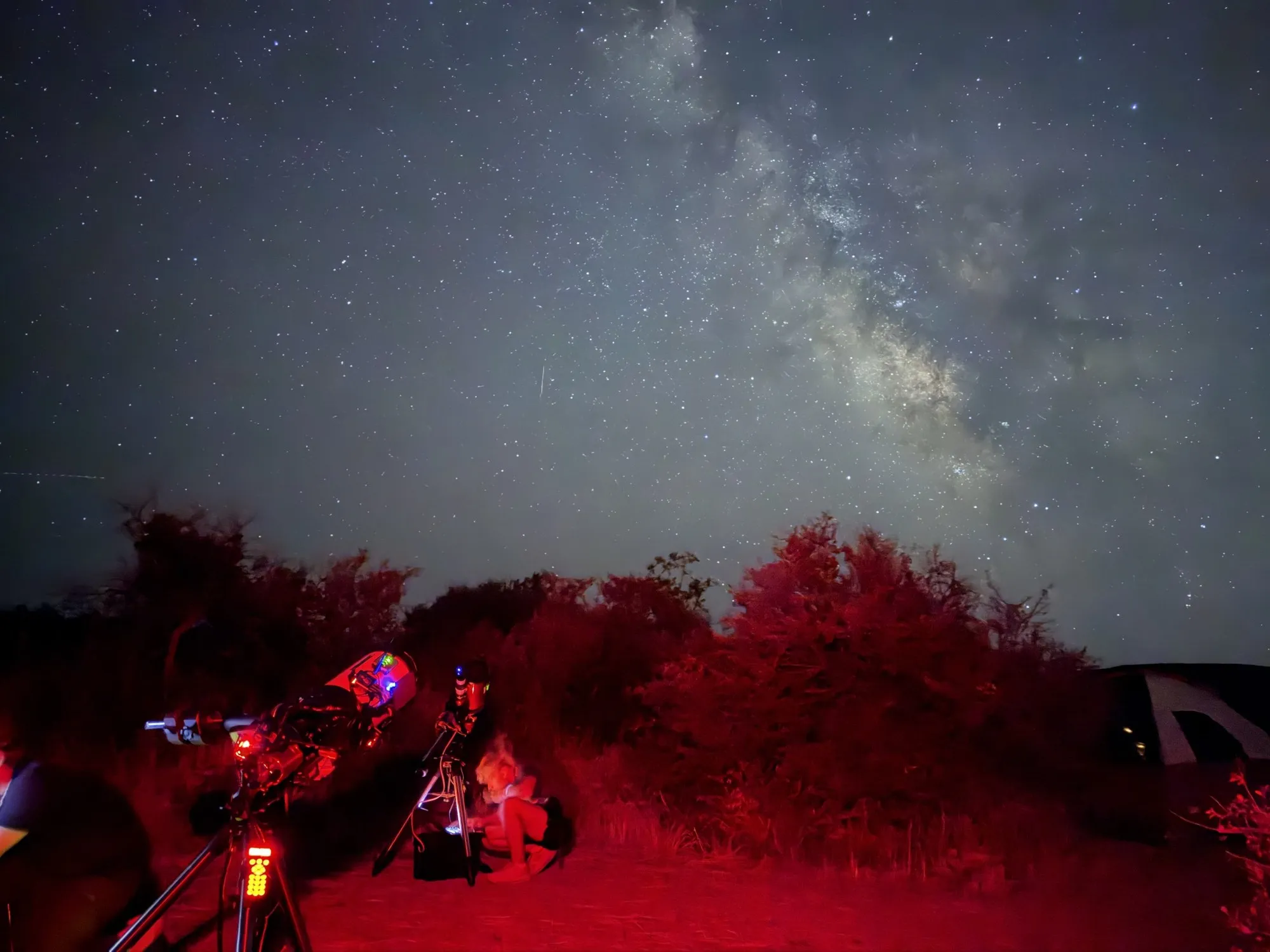
Imaging at a dark-sky site under the Milky Way. 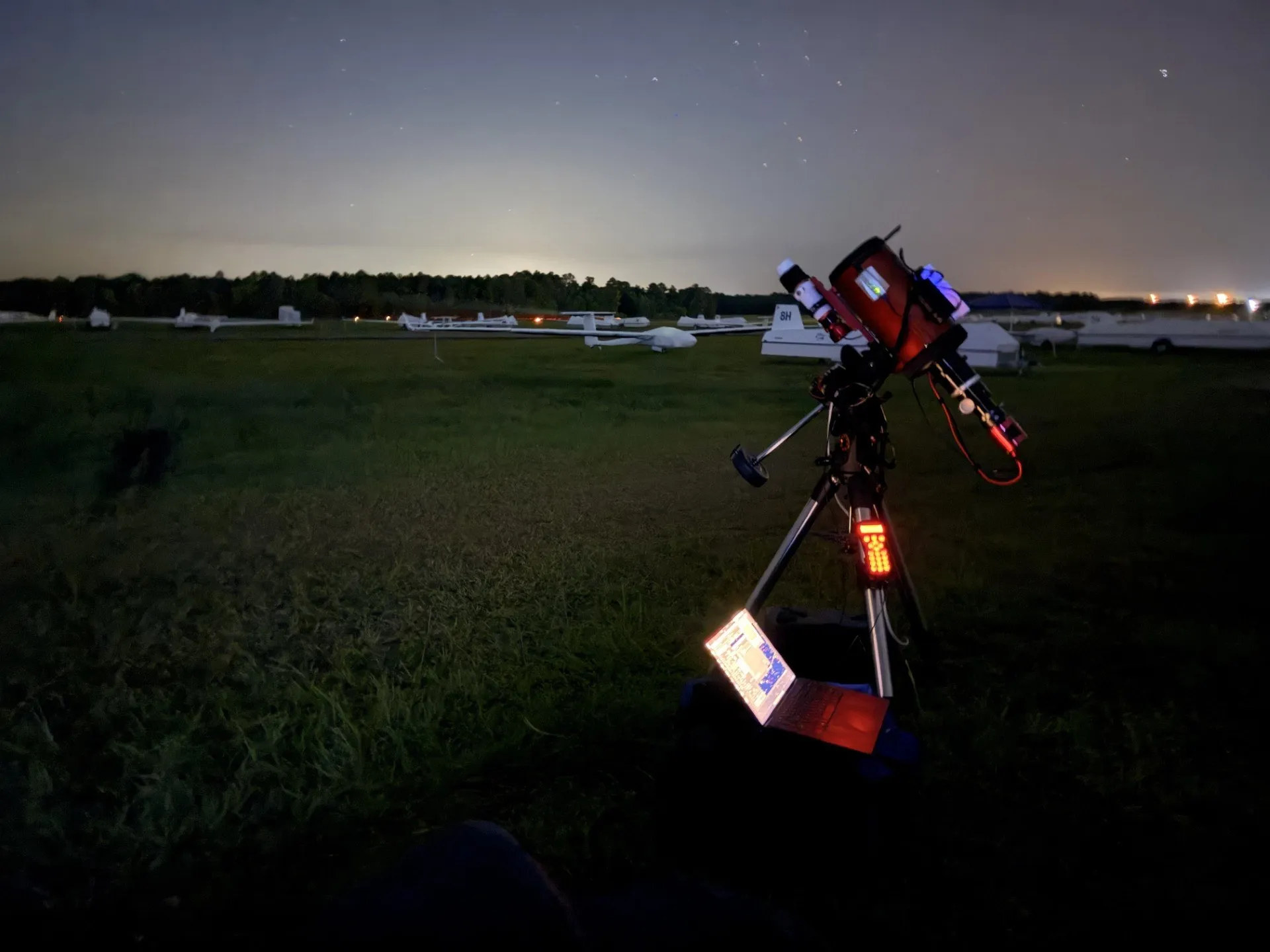
Setting up on a glider field at dusk. 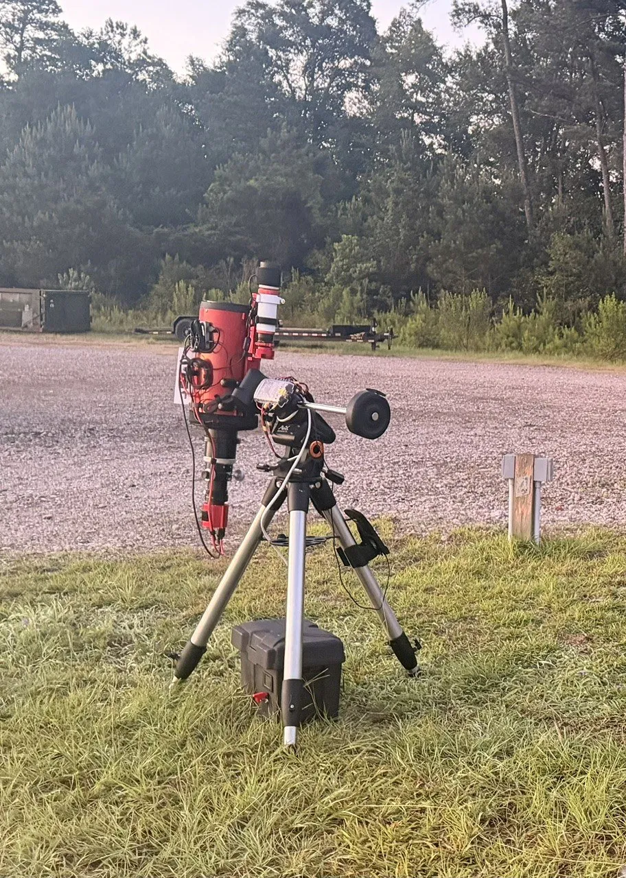
Daytime setup, with the power system under the tripod. 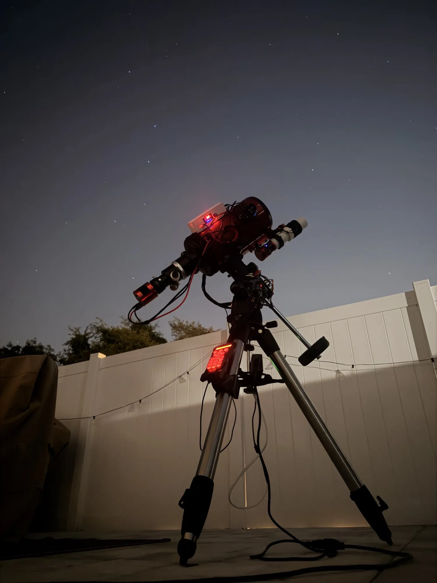
A backyard session, fully cabled.
Overview
This is a complete imaging observatory that fits in a car. It carries its own power, its own computer, and its own network, so it runs the same way in a dark-sky field with no internet as it does at a remote host site where I’m miles away.
I started it because of what I was learning in my astrophysics degree: I wanted to observe on my own, and I wanted to learn the skills that working at a professional observatory takes by building one myself. It also gave me a hard, open-ended engineering problem to work on. For now it travels with me, but I made it fully remote-capable from the start. I sometimes leave it set up temporarily at an observing field in Chiefland, Florida, and I plan to mount it permanently at a remote site.
Requirements
| # | Requirement | How it’s met | Status |
|---|---|---|---|
| R1 | Self-powered. Run a full night of imaging with no mains power. | Custom battery box feeding a custom power-distribution unit | Met: ≈30 W total draw; routinely two nights per charge |
| R2 | Operable on-site with no internet. | Mini PC starts its own Wi-Fi access point; laptop connects over RDP | Met |
| R3 | Operable fully remotely. | Mini PC joins the host site’s Wi-Fi; I connect over a WireGuard VPN | Met |
| R4 | Guiding at or below one imaging pixel (0.70″). | Hypertuned mount + PHD2 on a separate guide scope | Met: 0.7″ RMS in poor seeing, 0.4″ in excellent seeing |
| R5 | Accurate pointing and polar alignment after every setup. | TheSkyX calibration with a TPoint model | Met: ≈7″ total pointing RMS |
| R6 | Dew-free optics all night. | Custom PWM dew-heater controller | Met |
| R7 | Unattended imaging sequences. | N.I.N.A. sequences with PHD2 guiding | Met |
System architecture
Everything hangs off two paths. On the power path, a custom 642 Wh battery box feeds my distribution unit, which supplies every subsystem, including the mini PC mounted on the optical tube. On the control path, that mini PC drives the mount and both cameras over USB, and an ALFA Wi-Fi adapter connects it to me, either directly or through a VPN.
Subsystems
Optics and detectors
| Component | Choice | Key numbers |
|---|---|---|
| Imaging telescope | Photron RC6, 6″ Ritchey–Chrétien | 152 mm aperture, 1370 mm f/9 |
| Imaging camera | ZWO ASI294MC Pro (cooled, one-shot color) | 4144 × 2822 px, 4.63 µm pixels |
| Imaging scale | 0.70″ per pixel, 48′ × 33′ field | |
| Guide scope | William Optics 50 mm, on a custom underslung mount | ≈200 mm focal length |
| Guide camera | ZWO ASI224MC | 3.75 µm pixels, ≈3.9″ per pixel |
I image mainly at the RC6’s native 1370 mm, so the camera samples at 0.70″ per pixel, finer than typical seeing. The 200 mm guide scope samples at about 3.9″ per pixel, and PHD2’s sub-pixel centroiding still resolves corrections far below that.
The underslung guide scope. At first, the imaging train put far too much mass at the back of the tube. I moved the guide scope onto a custom mount under the front of the tube, where it acts as a counterweight to the imaging train. The cost is a small increase in the load’s moment of inertia, since that mass now sits farther out. In return, the evened-out mass distribution fixed the slow guide response and the flexure the mount had been fighting. On the mount, the inertia penalty turned out to be negligible.
Mount: hypertuned Celestron AVX
The AVX is an affordable, portable mount, but out of the box its factory grease, plastic bushings, and loose gear mesh limit how well it can guide. Guiding RMS was about 2.5″. I hypertuned it myself:
- Full teardown of the mount down to its individual components.
- Degreasing and ultrasonic (sonication) cleaning of every moving part to strip out the factory grease and debris.
- Re-greasing only the contact points, with a controlled amount of grease rather than the factory packing.
- Brass bushings in place of the plastic ones. Some I fabricated, some I bought. They hold tighter tolerances and wear far longer.
- Precise worm-to-gear tensioning during reassembly, tuned to cut backlash without making the gears bind.
| Before | After | |
|---|---|---|
| Guiding RMS | ≈2.5″ | 0.4–0.7″ |
That’s a 4–6× improvement. It turned the mount from the limiting factor into something that guides below one imaging pixel.
Guiding
PHD2 guides from the ASI224MC on the 50 mm guide scope. The guiding RMS is about 0.7″ in poor seeing and as low as 0.4″ in excellent conditions. At 0.70″ per imaging pixel, that keeps guiding error at or below one pixel even on bad nights, and well under the seeing disk.
Power distribution
Power comes from two custom units, connected with XT30 connectors throughout.
The battery box is the black case under the tripod. I built it around an ExpertPower 50 Ah battery (642 Wh), with a shunt-based inline power meter that tracks the energy used over an imaging session and a master power switch for the whole rig.
The distribution unit on the telescope takes that single feed and supplies every subsystem: the mount, the cooled imaging camera, the mini PC on the optical tube, and both dew heaters. With one managed source instead of a tangle of separate supplies, much less cabling hangs off a moving telescope.
| Power | |
|---|---|
| Whole-rig draw | ≈30 W |
| Theoretical runtime | 642 Wh ÷ 30 W ≈ 21 h |
| In practice | Never run out in a night; two full nights per charge when switched off during the day |
Dew control
Dew control runs on a custom PCB that I designed in KiCad. There are two heaters:
- Main heater: on the metal cell that holds the RC’s primary mirror. A PWM driver on the board sets its power, and a potentiometer lets me fine-tune the heat to the night’s humidity. In practice the secondary mirror hasn’t needed a heater of its own.
- Guide-scope heater: around the guide scope’s objective lens. The strap is rated for 5 V, so the board includes a 12 V → 5 V buck converter to run it. It has a single fixed setting, because the guide scope never showed overheating or heat-driven distortion that would need finer control.
Compute and network control
A Mele Quieter 4C fanless mini PC is mounted on the optical tube and runs everything. The network behavior is what makes the rig “remote-capable”:
- When the system powers up, the mini PC brings up an ALFA Wi-Fi adapter.
- On-site: it starts its own hotspot. When I’m in range, my laptop joins it and I control the scope over Remote Desktop (RDP). No internet needed.
- Remote: it joins the host site’s Wi-Fi network instead, and I reach it from anywhere through a WireGuard VPN, again over RDP.
Software stack
| Task | Software |
|---|---|
| Calibration, polar alignment, pointing model | TheSkyX with the TPoint module |
| Imaging sequences | N.I.N.A. |
| Autoguiding | PHD2 |
| Remote access | Windows RDP, over the hotspot or WireGuard |
| Processing | PixInsight |
Key engineering challenges
The four hardest parts of the build:
- Control system. Getting the mount, both cameras, TheSkyX, N.I.N.A., and PHD2 working together reliably on one headless mini PC.
- Mount hypertuning. Taking a consumer mount from ≈2.5″ to 0.4–0.7″ RMS guiding.
- Power distribution. Developing, designing, and building a unit that runs the whole rig off one battery.
- Network control. Making the system reachable both with no internet at all and from anywhere, with no changes when I switch between the two.
Case study: the Raspberry Pi that couldn’t keep up
The first version of the rig ran on a Raspberry Pi 4. Just getting it working was a project: I had to configure Raspberry Pi OS to start its own hotspot on boot so I could reach it over VNC, and that took even longer once the ALFA Wi-Fi adapter was involved. With that working, I ran imaging and mount control through KStars/Ekos, with PHD2 guiding.
Symptom. Guiding performance was poor, much worse than the mount should have allowed.
Ruling things out. I worked through every guiding setting in PHD2 and made sure the hardware was in perfect condition. Neither made a real difference, so the problem had to be somewhere other than the mount or the tuning.
Root cause. Watching CPU utilization during a guiding run gave it away. At short guide exposures (under 0.5 s), the guide-camera frames were saturating the Pi’s USB bus, and the Pi didn’t have the compute to centroid stars and calculate corrections fast enough. The guider was always working from stale data.
Fix. I replaced the Pi with the Mele Quieter 4C mini PC. It brought an x64 operating system, a faster USB bus, and far more compute, and moving to x64 Windows also opened up N.I.N.A. and TheSkyX. It also meant a second round of the network work: rebuilding the boot-time startup and the ALFA hotspot/remote integration from scratch on the new machine.
Result. The compute bottleneck was gone, and together with the mount hypertuning, the rig now guides at 0.4–0.7″ RMS.
Design decisions
| Decision | Alternatives | Why I chose it |
|---|---|---|
| Ritchey–Chrétien optics | Refractor, Schmidt–Cassegrain | Low cost per inch of aperture. The two hyperbolic mirrors make it aplanatic, meaning it’s free of spherical aberration and coma by design. All-reflective optics add no chromatic aberration. It also gives a wide, usable flat field for a large sensor. |
| Underslung guide scope | Guide scope on top of the tube, off-axis guider | It counterweights the tail-heavy imaging train. That fixed the guide-response and flexure problems for a negligible inertia cost (details). |
| Mini PC on the tube | Raspberry Pi 4 (the original), laptop | The Pi couldn’t handle fast guiding (USB and compute limits). The mini PC gives x64 software, a faster USB bus, and much more headroom (case study). |
| Own hotspot + WireGuard | Port forwarding, commercial remote-desktop services, a dedicated controller like ASIAIR | I already knew how to set it up reliably, and it works with or without internet. I’ll revisit it for a permanent install. |
| Custom power distribution | Commercial powered hubs | Cheaper and more customizable than what’s on the market, and I enjoy the electrical engineering involved. |
Validation: what it produces
- Deep-sky imaging of galaxies, nebulae, and supernova remnants, including 10.8 hours on M101 across several nights.
- Solar-system imaging of the Moon and the Sun.
The full set is in the astrophotography journal.
What’s next
Once the rig is permanently mounted, I want to move from imaging into science data:
- Time-domain photometry for large surveys like the AAVSO’s variable-star program.
- A dark-nebula survey. Using multi-night, deep integrations on objects in Lynds’ Catalogue of Dark Nebulae (LDN) to catalogue the faint, extended structure that shallower surveys miss.